Varied individual solutions for application-specific machines and devices
In order to meet the pressure to optimize processes with constantly increasing quality requirements, economic and rational production is a basic prerequisite.
This is why devices are still gaining importance where workpieces cannot be machined at all or only very cost-intensively or with insufficient precision. This plays an important role in both individual and small series production as well as in series and mass production.
We offer you complete customer-specific solutions for the device construction. Based on our many years of experience, we can offer you all types of devices, from simple mechanical to complex devices including hydraulic, pneumatic and electronic components such as hardware and software programming.
For individual requirements and difficult framework conditions, we develop, project and manufacture tailor-made special machines and equipment in order to efficiently automate even complex tasks.
If you can no longer rely on standard solutions for your complex tasks, please contact us. As a competent partner, we meet your challenges.
Product examples for special devices and machines
Turning device for spring carrier
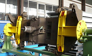
This application-specific turning device is used to accept spring carriers for the chassis of DB passenger coaches for repair welding on these assembly groups.
Spring carriers of different designs can be positioned in this special device. The spring carriers are fixed at distinctive points and can be turned into the most favorable welding position and in 45° steps by means of a manually operated self-locking angular gear and fixed in this position by means of an automatically acting locking mechanism.
The turning device consists of two mounting brackets (with and without rotary drive) as well as two connecting struts. The support arms are located on the support brackets. These can be adjusted approximating to the center of gravity of the spring carrier.
Dimensions ( L x W x H ): 3,755 x 1,400 x ca. 975 mm
Weight: approx. 670 kg
Benefits/ advantages
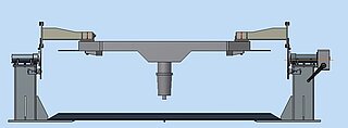
- time-saving clamping technology
- ergonomic working height
- easy handling
Pivoting and turning device for spring carrier
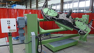
The spring carrier is clamped on this customized device for the leak test and by means of a hydraulic pump it is filled with anti-corrosive oil up to a pressure of 10 bars.
After the pressure test the oil is pumped out again. In order to drain the remaining oil, the spring carrier on the tilting and turning device is tilted around its longitudinal axis (x) and turned around the z-axis.
Structure of device
The two rotary stands are connected by a frame, which is driven on one side by an attached motor. There is a swivel frame mounted between the rotary stands. The swivel frame is connected to the actual mounting plate (swivel frame) of the spring carrier by a ball bearing slewing ring, at the teeth of which another motor engages.
The system is completed with an oil drip pan which is covered with a grid.
Technical data
All data can be adjusted according to customers`or application-specific requirements
| Dimensions: | Working table height: | approx. 1,300 mm |
| Height with device elements: | approx. 2,000 mm | |
| Width: | approx. 1,400 mm | |
| Length: | approx. 4,500 mm | |
| Weight: | approx. 2,200 kg | |
| Permissible load capacity: | approx. 1,000 kg | |
| Oil drip pan: | Capacity: | 230 l |
Benefits/ advantages
- time-saving clamping technology
- high working comfort
- easy handling
- draining of remaining oil by tilting and turning
Assembly and tilting device for transformers
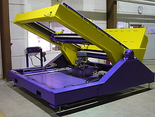
This individual device tilts transformers with variable dimensions between (L x W x H) 1,000 x 500 x 300 mm up to a maximum size of 2,500 x 2,200 x 900 mm and a mass of 20 t by 90°.
For the installation resp. repair, the transformers are positioned on four adjustable supporting points, locked and then tilted by 90°.
The mobile transformer tilting device consists of a base frame on which a pivot-mounted tilting frame is fixed. The base frame stands on adjustable feet. At the front part of the tilting frame a support plate is mounted which serves as a limit stop or footprint for the tilted transformer.
The complete assembly tilting device can be transported by means of a crane or an 8 t forklift truck.
Technical data of the device
All data can be adjusted according customers`or application-specific requirements
| Device dimensions: | Length: | approx. 3,260 mm |
| Width: | approx. 3,000 mm | |
| Height basic position: | approx. 3,100 mm | |
| Height tilted: | approx. 1,910 mm | |
| Load capacity: | approx. 20 t | |
Benefits/ advantages
- optimim accessibility
- can be used for many variants
- ergonomic working
- device is mobile
Transformer press
In the transformers of electric rail vehicles there are at least two large wound wire coils on a metal frame. Due to relatively small quantities and the wide variety of versions, some spools are only wound semi-automatically.
In order to reduce the gaps caused by winding and thus to increase efficiency, the coils must be compressed with very high forces and then locked accordingly. The transformer press, which was developed and built according to customer’s requirements, serves this purpose.
Structure and function of the press
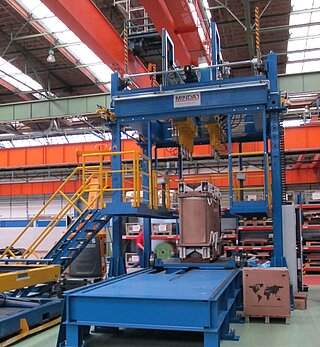
Basic structure:
The press consists of a frame with a lower part with a rail lift. On the frame there is a spindle lifting unit, which allows adjusting the height of the upper part of the press.
The upper part of the press consists of a frame, two hydraulic traverses and an adjustment drive for the traverses. There are four pressure cylinders on each traverse.
The operator can move the pressure cylinders to the pressure position in touch mode via a walkway consisting of a ladder and various platforms.
At floor level there is an extendable platform from which a rail-guided carriage transports the transformers into and out of the press frame by means of a chain conveyor.
The entire press area is protected by a safety fence.
Functions:
A transformer is mounted on the carriage, which is located on the exit platform. The safety circuit is activated.
The operator selects the transformer type to be processed on the panel. The transformer automatically retracts into the press. In touch mode, the pressure cylinders are positioned on the pressure points and then lowered.
Pressing takes place automatically, as does the subsequent extension of the transformer. When the transformer is driven out, the press data, the time and the data of the transformer are stored.
Technical data
| Press dimensions: | Length: | 8,040 mm |
| Widths (without stairs): | approx. 4,500 mm | |
| Height: | approx. 6,640 mm | |
| Transformers dimensions: | Height (min./max.): | 1,290/ 2,350 mm |
| Width (min./max.): | 480/ 1,480 mm | |
| Weight max.: | 18 t | |
| Weight: | Dead weight press: | 33 t |
| Lift stroke: | Press upper part, vertical: | max. 950 mm |
| Press cylinder, vertical: | max. 300 mm | |
| Pressing force, total: | 8 Cylinders à 200 kN: | 160 t |
Benefits/ advantages
- high process accuracy
- high repeat accuracy
- can be used for many variants
- Positioning of pressure cylinders in x, y and z-direction possible
- ergonomic working
- safe handling
Conveyor technology wheelset storage
This system serves on the one hand to provide empty pallets and on the other hand to discharge pallets with wheelsets. The challenges in this application were the limited existing structural conditions.
General structure of the transport system
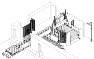
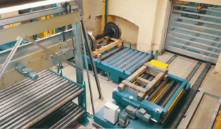
The conveyor system consists of a two-storey driven roller conveyor with a pallet magazine positioned above it. The plant also includes a driven heavy-duty roller conveyor as well as a transfer car with lifting table and heavy-duty roller conveyor including the associated rail system.
Since the system extends over two adjacent buildings, a high-speed door was installed at the transition, which was integrated into the control and safety concept of the system.
A comprehensive safety technology in form of sensors, light barriers and safety fences as well as a protection against fork lifts for the roller conveyors complete the transport line.
Functions of the system
In the lower level of the two-storey roller conveyor, up to five small empty pallets are buffered, which are positioned by a fork lift. In the upper level there are stacks with large empty pallets, which are also stored by the fork lift. The large pallets are automatically separated by the pallet magazine (portal gripper).
At the operator's request, the empty pallets are provided automatically. For this purpose, the rail-bound car travels to the other part of the building and picks up the selected pallet (small, large). In order to pick up empty pallets from both levels of the roller conveyor, the heavy-duty roller conveyor of the transfer car can be lifted to the upper level by means of a lifting table.
After the empty pallet has been picked up, the car automatically returns to its initial position. There, after the final diagnosis, the operator positions the wheelset on the pallet by means of a crane. For this purpose, the transfer car including the roller conveyor can be moved manually within certain limits in order to position the wheelset exactly on the pallet.
The car then moves automatically to the other area and transfers the pallet with the wheelset to the heavy-duty roller conveyor, which is also used for buffering purposes. The pallets with the wheelsets are then picked up by the fork lift and sent to the dispatch area.
The transfer car immediately picks up the next pallet requested and returns to its starting position.
Technical data
| Heavy-duty roller conveyor, with protection against forklifts | Empty pallet roller conveyor (2 levels), with protection against forklifts | Transfer car | Pallet magazine (incl. supporting struts) | ||
|---|---|---|---|---|---|
| Dimensions: | Total length: | approx. 4,332 mm | approx. 3,956 mm | approx. 3,064 mm | 1,630 mm |
| Total width: | 2,250 mm | 2,250 mm | 1,450 mm | 4,240 mm | |
| Total height: | approx. 662 mm | approx. 1,626 mm | 675 mm | approx. 3,100 mm | |
| Working height: | 550 mm | 550 / 1,180 mm | 550/ 1,180 mm | ||
| Payload: | 3,000 kg | 1,000 kg (per level) | 3,000 kg | 500 mm | |
| Drives: | Roller conveyor: | 0.75 kW | 0.37 kW | 0.75 kW | |
| Moving drive: | 0.55 kW | ||||
| Lift stroke: | 1.1 kW | 1.1 kW | |||
| Gripper: | 0.25 kW |
Benefits/ advantages
- shortened cycle times
- more efficient procrsses
- compact design
- reduction of downtimes
- optimal use of the building
Further application-specific devices
1. Assembly stand for gearboxes
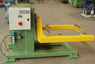
This application-specific rotary assembly stand is used for gearbox assembly as well as for reconditioning.
This device allows turning gears up to a dead weight of 800 kg by 360° during the installation.
For maintenance processes, this rotary stand can also be installed in an oil drip pan.
The gear jack consists of a base frame to which a gear holder is attached via a shaft. The jack is driven by an electric motor. A brake disc with pneumatically actuated brake caliper provides an additional safety function so that plant safety is ensured in the event of shaft breakage or motor defect.
The device can be stopped in any position.
Dimensions: 1,135 x 1,060 x 1,120 mm
(L x W x H in basic position)
Air pressure: min. 5 bar
Benefits/ advantages
- optimum accessibility
- ergonomic working
- by means of an adapter the unit can be used for different variants
- high work safety
2. Turning device for Voith-gear
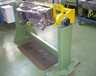
This customized turning device for Voith gears is used for the safe positioning of gears during dismantling and installation work for vehicle repairs.
For all tasks, the turning device can be turned in a safe and protected position.
The turning process is possible at +90° and -90° starting from the vertical 0° position.
Dimensions (L x W x H): 2,365 x 800 x 1,120 mm
Load capacity: max. 350 kg
Benefits/ advantages
- optimum accessibility
- ergonomic working
- high work safety
3. Pull-off device for stabilizer
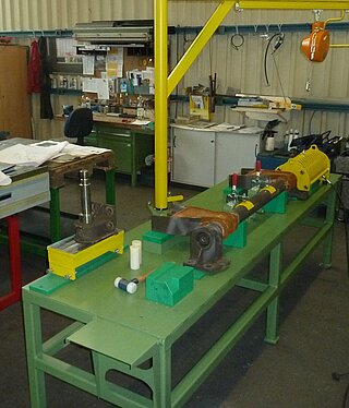
At this workstation, this special device pulls off support frames from stabilizers and pushes them on. After removing the support frames, the ultra-bushes (elastomer bearings) contained therein are replaced by means of special punches on a column press belonging to the workplace.
The device consists of a worktable with table extensions on both sides. On the worktable there are two prism supports on which the stabilizers are positioned. A pull-off unit, which is a separate component, has, among other things, a basket to protect against falling parts. The push-on device has a similar design.
A balancer with swivel arm supports attaching the heavy pull-off or push-on device.
The push-out and push-in device is a tool which, together with a corresponding punch, is used to push out and push in the ultra-bush under the column press.
- Dimensions (L x W x H): approx. 2,800 x 800 x 1,050 mm
(height with device) - Weight: approx. 250 kg
Benefits/ advantages
- ergonomic working height
- high process reliability
- Work facilitation
- Increase in productivity
Further MINDA solutions for railway technology devision
Application-specific devices and systems
Our services and fields: