Customer- and application-specific solution for bogie and wheelset handling
A bogie consists of a frame to which other parts such as wheelsets and springs are attached. They all carry the entire weight of the vehicle at high speeds and at the same time guide the rail vehicle on the track.
The reconditioning and maintenance of wheelsets and bogies is therefore essential for the maintenance, function and safety of rail vehicles.
Therefore, highest attention must be given to the optimization of the maintenance processes.
We at MINDA support you in this respect. We implement your specific requirements and specifications with our individual solutions for you.
Product examples for bogie and wheelset handling
Tilting device for bogies
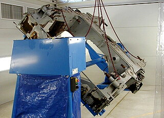
Different types of bogies are clamped on these customized tilting devices and during the painting process they are tilted by ± 45°. This device is driven hydraulically. The stop positions are protected by mechanical interlocking even in case of pipeline damage.
This application-specific turning device is also used for maintenance, cleaning, repair and servicing tasks.
Structure of the tilting device (or turning device)
The tilting device consists laterally of two bearing blocks, between which there is a mounting frame. On the mounting frame there are 4 clamping devices on which the bogie is mounted. The device is fixed to the floor.
A bearing block contains a generously dimensioned drive to cope with the bogies' centers of gravity which might not be located in the axis of rotation. The drive side is protected by a mounted protective hood.
The opposite bearing block can be moved and locked on rails to compensate for different lengths of the bogies.
The electrical control cabinet and the hydraulic unit with attached valve technology are located on a rack outside the spraying booth.
Procedure/ Function
A suitable hoist and 4 rope suspensions are required to insert the bogie into the tilting device. After the bogie frame has been positioned exactly on the 4 clamping devices, the frame is fixed by means of clamping claws.
The tilting process is initiated by extending or retracting a hydraulic cylinder. When the tilting position is changed into the desired direction, the lock is released and the tilting process begins. When the bogie is in the desired position, locking takes place.
Technical data
All data can be adjusted according to customers`or application-specific requirements.
Dimensions
Length: 5,800 mm
Width: 2,400 mm
Height: 1,320 mm
Benefits/ Advantages
- the customer-specific device is manufactured in EX-protection version
- maximum component size L x W: 8,000 x 3,200 mm
- very good access during the painting process
Wheelset drop system (exchange of wheels)
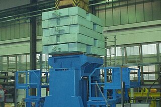
The wheelset drop (wheel changing device) is used to lift and lower rail vehicle cars for changing the bolster springs from bogies and for transporting rail vehicle parts (max. 25 t) as well as for transporting the dismantled wheelsets.
It is driven via a belt driven spindle-type lifting gear. The traversing is controlled via remote control.
Basic structure of the wheelset drop system
The wheelset drop system consists of a welded base frame to which a rail-guided travel drive is attached. The travel drive is driven by an electric motor.
There is a lifting frame on each long side. These lifting frames accept a lifting spindle and two linear guides, which guide the lowering table when lateral forces occur.
Platforms are mounted on both sides of the wheelset drop. Two flaps in the platform surfaces enable the transport of rail vehicle parts with a maximum weight of 2 tons.
Technical data
All data can be adjusted according to customers`or application-specific requirements
Dimensions
Length: 3,460 mm
Width: 1,925 mm
Height: 1,917 mm (basic setting)
Lowering table stroke: 1,550 mm
Max. lifting power: 25 t
Benefits/ Advantages
- low construction with high lifting heigth
- high comfort and good safety equipment
- good maintenance conditions
Lifting and rolling device for wheelset
This semi-automatic lifting-rolling device allows to lift and lower wheelsets between different infeed and outfeed levels. Moreover, the wheelsets can be lifted to ergonomic height for different operations, such as repair, maintenance, painting or cleaning.
Driven contour rollers allow rotating the wheelset in order to reach every position of the wheelset during different operations.
Structure of the customer-specific device for wheelsets
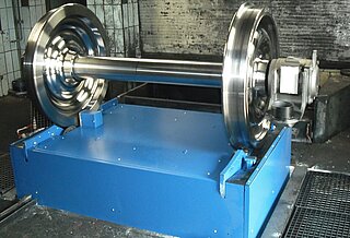
The lifting-rolling device is located on a lifting table, which lifts or lowers the device to working level, ejection level and lifts or lowers the maintenance level. This device can be designed for a fixed track width or also for adjustable track widths.
Furthermore, the device has two final position stoppers, whereby the shock is cushioned by shock absorbers. A backstop prevents the wheelset from rolling back. An ejector serves to roll out of the device.
The lifting table itself is mounted on a steel frame underneath. The lifting and lowering of the lifting table is hydraulic.
This lifting-rolling device is embedded in a pit on site.
Functions of the lifting-rolling device
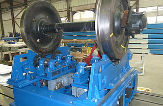
The machined wheelsets are rolled up from a wheelset magazine onto this application-specific device via a feed track. The infeed rail is lowered and the wheelset is softly positioned onto the rollers.
During painting, the wheelset is rotated via driven contour rollers. The speed, which depends on the viscosity of the color, is infinitely adjustable.
After the painting process, the lifting-rolling device is lowered to the roll-out level by 435 mm and the wheelset is discharged by means of an ejector. The wheelset rolls over a special wedge up to 6 m on the roller track.
This device can be moved to an upper position (900 mm above the feed track) for carrying out maintenance work.
Technical data
All data can be adjusted according to customers`or application-specific requirements.
| Device structure | Steel frame | Lifting table | ||
|---|---|---|---|---|
| Dimensions | Length: | approx. 1,800 mm | approx. 2,050 mm | 1,750 mm |
| Width: | approx. 1,225 mm | approx. 1,800 mm | 1,150 mm | |
| Height: | approx. 1,450 mm | approx. 3,050 mm | 400 mm | |
| Load carrying capacity: | ---- | ---- | 4,000 daN |
| Device with: | fix track width | adjustable track width |
|---|---|---|
| Tread diameter: | 680 - 1,000 mm | 500 - 1,003 mm |
| Wheelset track widths: | 1,435 mm | 900 - 1,700 mm |
| Wheelset weight: | 800 - 3,000 kg | 800 - 3,000 kg |
| Rolling speed: | max. 30 rpm | max. 30 rpm |
Benefits/ advantages
- The rolling device is EX-protected for zone 2.
- no crane required
- ergonomic working height
- high work safety
- for manual and automatic operation
Lifting, Rolling and turning device for wheelset
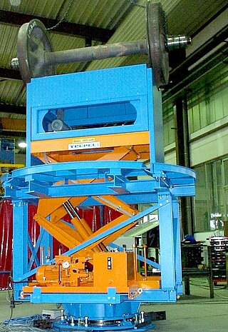
This customer-specific lifting-rolling-turning device is used for lifting and turning wheelsets with and without attachments with fixed track width.
On site, this device is embedded in a pit. A gear rim turntable is mounted on the pit floor and driven by an explosion-proof frequency-controlled motor. A hydraulic fork lifting table is mounted on this turntable, which achieves a lifting movement of approx. 1,150 mm.
The roller unit, which rotates the wheelset around its axis, is fixed on this lifting table. Four contour rollers guide the wheelset.
The wheelsets can be picked up and delivered via the turning function from 90° and 180° direction. A wheelset is set to working height by means of a fork lifting table and turned via the roller drive. The wheelset roller device is also frequency controlled.
Technical data
All data can be adjusted according to customers`or application-specific requirements.
| Dimensions: | Diameter: | 2,210 mm |
| Height: (basic position): | 1,600 mm | |
| Load capacity: | max. 2,500 kg | |
| Tread diameter: | 650 - 1,100 mm | |
| Track width: | 1,425 mm |
Benefits/ advantages
- good accessibility
- narrow design
- ergonomic working height
- hazard-free work
- Plant designed with EX-protection
Other application examples for wheelset handling
1. Roller stand resp. turning device for wheelsets
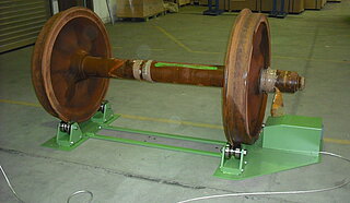
These devices are used to displace wheelsets with and without gears in direction of rotation. Four profile rollers, one of them is driven, support the wheelset. These devices are used for inspection and repair work.
During maintenance work, this ensures e.g. when the wheelsets are dismantled, a regular grease distribution in the wheelset bearing. The rotational speed of the wheelset can be adjusted via a panel or control console.
This device is available in different versions. The roller stand can be used stationary by being firmly connected to the hall floor. The device is equipped by means of a crane and slings..
- Dimensions (L x W x H ): 2,181 x 834 x 219 mm
- Load capacity: max. 2,500 kg
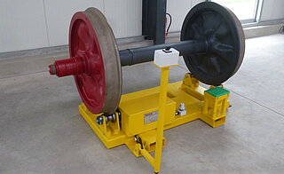
However, the turning device can also be designed as a mobile version. The device is equipped with so-called forklift shoes to enable the entire unit to be transported by forklift truck. In order to additionally store this special device in a space-saving manner, the control console can be retracted.
- Dimensions L x W x H: 1,260 x 1,578 x 1,030 mm
(control panel extended) - Dimensions L x W x H: 1,030 x 1,578 x 400 mm
(control panel retracted)
- Net weight: 370 kg
Benefits/ advantages
- ergonomic working height
- good accessibility
- hazard-free work
- space-saving storage of the device
2. Driven bench grinder for wheelset shafts
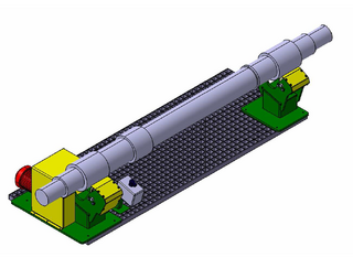
During grinding operations, the wheelset shafts are placed on this driven roller block and rotated continuously. The shafts are positioned by means of a crane.
The device consists of two holders, each with two axle holders, between which the shaft is accommodated. A drive motor, which has been partially equipped with a cover, is mounted on a holding fixture.
A switch console completes the device.
Dimensions L x W x H: 1,755 x 560 x 310 mm
Load capacity: max. 300 kg
Benefits/ advantages
- ergonomic working
- strength-saving work
- increase of work safety
3. Rolling device for individual MT (magnetic particle) wheel inspection
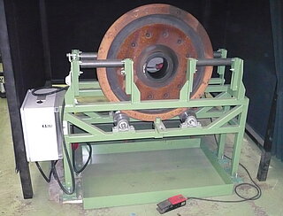
The mounting device is used for non-destructive testing during wheel maintenance for the assembly, guidance and rotation of the wheel discs during the magnetic particle testing.
For this purpose, the wheel discs are positioned in upright position on the device, where they are safely guided laterally, while being set into regular rotation.
The monitor is operated via a foot switch; the rotational speed can be set from 2 - 12 rpm.
Dimensions ( L x W x H): 1,400 x 777 x 1,040 mm
Load capacity: max. 750 kg
Benefits/ advantages
- ergonomic working
- easy handling
- hazard-free work
- very good accessibility
Further MINDA solutions for railway technology devision
Application-specific devices and systems
Our services and fields:
