Tailor-made solutions in every detail
You cannot find a suitable plant for your tasks? Then we are the right partner to contact! We do not manufacture anything "off the rack”, we realize your requirements.
With our comprehensive expertise and many years of experience, we develop and implement tailor-made solutions; starting from transport and connecting technology, via robot applications up to complex handling tasks.
Everything from a single source - our range of performances offers you everything from development and realization to after-sales.
Transport system for refractory bricks
In this application, an automatic transport system for refractory bricks (from the brick press to stacking on the dispatch pallet) was individually designed for the customer.
Basic structure of the plant
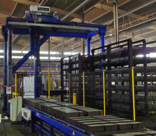
1. Trolley transport
1.1 Trolley transport with lowerable cam conveyors and chain transfer with magnetic gripper
1.2 Automatic cross transfer platforms (transfer cars)
2. Palletizing line
2.1 Unloading gantry for special stone pallets
2.2 Chain conveyors with infeed plates for alignment
2.3 Driven roller conveyors as conveyor and buffer sections
2.4 Manual deposit point: driven roller conveyor with lifting table
2.5 Empty pallet magazine
2.6 Lifting table with heavy duty roller conveyors
2.7 Right angle station
1. Functions of trolley transport
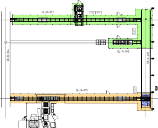
After the stone press, the stones are on special pallets, which are stacked in trolleys.
The chain transfer unit with magnetic coupling is used to transport the trolleys of up to 12 t. The chain transfer is installed next to the transport section, the carriage is modified for lateral conveying.
With this solution we have successfully combined the technology of the chain transfer unit, proven in the field of conveyor technology, with our experiences in magnetic clamping technology in the field of welding fixtures.
The cross shuttle cars are on rails and transport or distribute both empty and full trolleys to the different process lines. Pusher units are used to pick up and deliver the trolleys.
Advantages of this solution
- A magnetic gripping unit enables to pick up the trolley from an inaccurate starting position
- Fine positioning precise to the millimeter
- Low maintenance
- Also works in dirty environments
2. Functions of the palletizing line
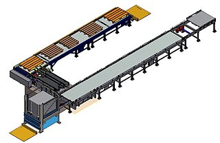
With the unloading gantry, the trolleys are automatically unloaded from bottom to top. The gantry can be moved horizontally and vertically. By turning the forks on the gantry, the pallets are placed on the chain conveyor. A driven roller conveyor (also serves as buffer section) takes over the full pallet and transports it to the manual deposit station.
The driven roller conveyor at the manual deposit station is placed on a lifting table so that the removal height can be adjusted. The workplace is equipped with a vacuum lifting device to move the heavy bricks ergonomically. The bricks are stacked on a sales pallet, which is positioned on the lifting table with heavy-duty roller conveyor. By defined lowering of the lifting table, the bricks can be stacked in several layers one above the other on the sales pallet.
The empty special pallet is transported into the pallet magazine at the push of a button. The loaded sales pallet is then transported to the right angle station.
The right angle station transports the sales pallet turned by 90° to the discharge section.
Technical Data
Transport length (total): approx. 50 m
Max. weight per trolley: 12 t
Max. weight sales pallet: 2 t
Processing section for concrete pipes
This plant carries out all work steps after the tempering of the concrete pipes. For concrete pipes with different diameters, the transport, the defined tilting of the pipes, the roughening of the pipe ends as well as the cleaning and marking can be carried out automatically. .
An automatic pallet handling system is integrated in the plant.
Customer benefits
- Numerous partial operations are fully automatically interlinked
- Transport and handling of various cross-sections
- Including handling technology
- PLC control and product tracking
- Plant can be extended by different options
Description of function
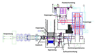
All pipes are taken vertically, on up to four pallets, standing upright from the tempering tunnel by a tilting car with vacuum suction cups and roller conveyor. By tilting the car, the pipes are discharged crosswise onto the conveyor line to the milling gantry.
The pallets remain sucked onto the car. After tilting back, the pallets are released by the suction units, moved against a limit stop and removed by a gantry with vacuum grippers and stacked in a defined place.
Special features / customer benefits
- The pallets are prevented from falling into the catch area of the tilting car
- Sensoric monitoring of the pallet positions
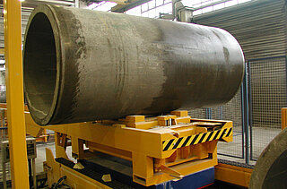
The concrete pipes are taken over from the milling machine by means of transport cars. This transport car, which is equipped with a lifting table, transports the pipes on a fixed transport section to the final processing.
The transport car transfers the pipe to a rolling device, which is used to turn the pipes during the further processing steps.
Special features
- The center distance of the rollers can be adjusted to the pipe type and diameter by electric motor.
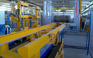
The final processing is done in 3 steps:
1. Roughening: By means of milling tools, which are pneumatically moved to the pipe and pressed against it, the pipe is roughened on both sides. This enables later gluing at these points.
2. Washing: The washing unit is located on a horizontally and vertically movable linear unit and serves to clean the areas to be printed.
3. Signing: Remaining water drops are blown off. The print head is located on a linear unit and can be moved horizontally and vertically.
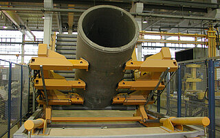
A difference is made between two objectives when transporting the pipes:
1. The transport car transports the pipe onto a heavy-duty chain conveyor, which transports the pipe to another processing step..
2. The transport car transfers the pipe to another tilting car, which takes the pipe with holding arms. The pipe is set up and can be removed by an indoor crane.
Conveyor line for molds and drying grates
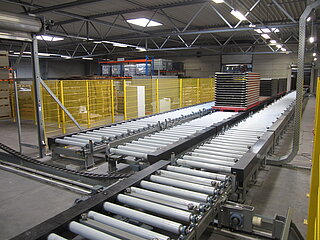
Molds and drying grates are required for the production of light-weight and concrete panels. As the quantities and varieties have increased, storage, buffering and automated circulation became very important.
The molds and drying grates are placed on top of each other and transported, buffered and stored in stacks. The appropriate design of the conveyor section provides a circulation possibility of the stacks and the possibility of pre-sorting was achieved.
A plant consists of 35 roller conveyors (divided into several lines) for the storage circulation as well as the provision according to demand and 3 rail-guided trolleys for the exchange with the production lines. Here the molds are separately placed on a chain conveyor, which then transports them to the next process. In an additional area, a further 21 roller conveyors (in 3 lines) and a transfer car were installed at a later date to ensure the supply and storage of mold stacks. A gantry for separation or stacking completes the entire system.
These areas are integrated into the overall concept of the plant with regard to their functions as well as in terms of data and control technology.
The entire area is delimited as a safety area.
Technical data
| Parameters | Roller conveyor | Transfer car | Chain conveyor |
| Length | approx. 3,300/ 6,500 mm | ca. 3,300 mm | 3,800 mm |
| Width | approx. 1,270 mm | approx. 1,300/ 2,300 mm | 1,585 mm |
| Height | approx. 600 mm | approx. 600/ 1,300 mm | 966 mm |
| Load capacity | 10 t | 10 t | 500 kg |
| Drive | 0.75 kW | 2.2 kW | 0.55 kW |
Transport line for panel molds and transport frames
In order to increase the customer's production capacity for drywall elements, it was necessary to integrate a new production line into an existing building. Due to the limited space available, the extension of the transport technology was challenging.
The automatic supply of the production line with panel-type molds stacked on a transport frame had to be ensured. On the one hand, the empty molds are stacked individually and fed to the production area and on the other hand, the empty transport frames have to be returned.
Description of function
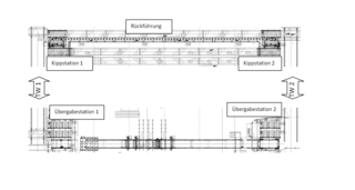
1. Feeding empty molds
A carriage (TC1) transports the mold stack on a transport frame to transfer point 1 (beginning of the production line). There, a portal gripper picks up individual molds and puts them on a chain conveyor, which then transports them to be filled.
The filled molds are transported to transfer point 2 by means of a chain conveyor and are then stacked again on a transport frame with another portal gripper. The transfer car (TC2) then takes the mold stack to the next processing station.
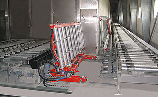
2. Return of transport frame
The transfer car TC1 transports the empty transport frames after stacking to the tilting station 1. The tilting car is a special construction that allows the transport frame to be turned by approx. 80° and then transferred to a vertical support roller conveyor (inclination approx. 80°).
At the end of the return line there is a second tilting car which picks up the transport frame and turns it back into the horizontal position. The transfer car TC2 transports the frames to their further place of use.
Special feature
With this solution for the return unit, the approx. 30 m long length transport can be realized under limited space conditions.
Conveyor line for MDF panel stacks
In order to increase capacities in MDF production step by step, it was necessary to adjust the existing logistics to future performance parameters. The aim was to provide sufficient transport capacities, including a buffer section, so that transports no longer had to be carried out by crane technology.
The modification of the new conveyor line had to be implemented without major structural changes. As the new line closed a gap, the new plant also had to be modified according to the existing systems with regard to working heights and transfer speeds.
Description of function

MDF-stacks are picked up by means of transfer cars from two separate production lines and transported to the new conveyor line. The conveyor line takes over the stacks and then transports them to the junction. On the basis of the transmitted data, the stack is either transported further or redirected into the area 2 via the right angle station.
The remaining stacks on conveyor line 1 are fed by another transfer car to another processing step.
Conveyor line 1 consists of a total of approx. 90 m plastic chain conveyors and a right angle station, which is equipped with both a plastic chain conveyor and a 4-lines chain conveyor for crosswise shifting.
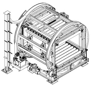
In area 2 behind the right angle station the stacks are also fed to the stack turner via plastic chain conveyors. If requested by the transmitted data, the MDF stack is turned by 180° in the turning device.
The turning device is equipped with two roller conveyors in the turnover station, one of which is height adjustable.
The stack is transported into the turning device, clamped by the roller conveyors and turned in 2 steps so that the individual panels of the stack can be aligned by sliding.
After turning, the stack is released again and transferred to a swinging car in area 3.
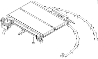
In the discharge area 3 the stack is transferred to the rail-guided swinging car after turning.
This swinging car is also equipped with a plastic chain conveyor. By means of this car the MDF stack is then transferred to other plastic chain conveyors.
Another transfer car (cross shuttle car) then takes the stacks from the conveyors and transports them to another processing area.
Special feature
The components of this plant are mainly customer-specific special designs for heavy-duty transport.
The plastic chain conveyors ensure a jerk-free as well as safe and smooth running for gentle stack transport. In this way the so-called "elephant foot" can be avoided.
Technical data
| Parameters | Plastic chain | Right angle station | Stack turner | Swinging car |
| Length: | 3,200 bis approx. 6,400 mm | 3,800 mm | 3,700 mm | 3,350 mm |
| Width: | approx. 3,100 mm | 4,200 mm | 3,800 mm | 3,620 mm |
| Height: | -------- | -------- | 4,600 mm | -------- |
| Working height: | 400 mm | 400 mm | 440 mm | 440 mm |
| Load capacity: | 8 bis 15 t | 8 t | approx. 8 t | approx. 8 t |
| Drive Conveyor | 3 kW frequency-controlled | 3 kW frequency-controlled | 1.5 kW frequency-controlled | 3 kW frequency-controlled |
| Turning drive: | -------- | -------- | 7.5 kW | -------- |
| Swivel drive: | -------- | -------- | -------- | 2.2 kW frequency-controlled |
Further MINDA solutions for building and insulation industry
Examples for realised conveyor systems
Our services and fields: